Breadboard Regulated Power Supply 5V/3.3V

Figure 1: Breadboard Power Supply on Breadboard
In any electronic product or project there is always a need for a source of power for the system to work. This is called a power supply. In this project we are going to design step by step a simple Breadboard Regulated Power Supply
The source of this power can come from different sources like the mains AC voltage, a battery or even from a renewable power source like a solar panel or fuel cell to name just a few.
The most common source of power is usually the mains AC, with this power, we need a transformer to convert the 220V 50Hz mains or the 120V 60Hz if you are living in the United States of America to a lower voltage required by the electronic circuit, this can be typically between 6V and 12V when 5V regulated DC is needed. Microcontroller based projects usually require a regulated 5V DC or 3.3V DC.
A breadboard is a piece of board for making temporary circuits and prototyping. The great advantage of using a breadboard is that it requires absolutely no soldering. All you need is to place your components and some few jumper wires and ready to test your project. Absolutely invaluable in prototyping especially for students.
That said, to get power hassle-free to power rails of a breadboard can be a challenge, you need a convenient and safe way to get either a regulated 5V DC or 3.3V DC depending on your application on your breadboard power rails.
This Breadboard power supply takes power from a 6 to 15V DC power supply and outputs a selectable 5V or 3.3V regulated voltage using a switch. This board can be easily inserted into a breadboard using a .1″ (2.54 mm) headers mounted on the bottom of the PCB. Pins labeled VCC and GND plug directly into the power lines of a breadboard. This Board can be used to power your prototyping project on Breadboard by providing a regulated 5V or 3.3V ideal for microcontroller projects. We’re gonna start from simulation, schematic and board layout design with EAGLE PCB Software then fabricate the boards with PCBWay a cheap PCB prototyping company based in China.
There are two pins available within the barrel jack footprint. Any stripped +/- DC supply can be connected instead of the barrel connector. Board has both an On/Off switch and a voltage select switch (3.3V/5V).
Watch the Video Tutorial:
1. Description of operation

Figure 2: Breadboard Power Supply Circuit Diagram
The board has two switches, the ON/OFF switch and the voltage selector switch to select 5V or 3.3V. The circuit is based around the LM317 voltage regulator.
The LM317 is an adjustable 3 terminal positive voltage regulator capable of supplying more than 1.5A over an output voltage range of 1.25V to 37V. This regulator is exceptionally easy to use and requires only two external resistors to set the output voltage, The R1 and R2 or R1 and R2 + R3 when SW1 is not grounded.

Figure 3: LM317 pinout
LM317 Features
- Output Voltage Range Adjustable From 1.25 V to 37 V
- Output Current Greater Than 1.5 A
- Internal Short-Circuit Current Limiting
- Thermal Overload Protection
- Output Safe-Area Compensation
The output of the LM317 variable regulator is determined by this simple formula:
V out = V ref x (1+R2/R1) + (I adj x R2) in this case R2 can be the sum of R2+R3 if SW1 is on position 5V. If SW1 is on position 3.3V, R3 is ignored because the current will flow to ground directly via the SW1.
V ref = 1.25V
I adjust = 50μA, this is too small and can be omitted, thus the formula becomes:
V out = 1.25 x (1+R2/R1)
Scenario 1: SW1 on position 5V:
V out = 1.25 (1 + ((390+330)/240) = 5
Scenario 2: SW1 on position 3.3V:
V out = 1.25 (1 + (390/240) = 2.281
For more information, please read the LM317 datasheet.
Buy the Breadboard Powers supply


2. Schematic design Using EAGLE
Any PCB Schematic design software can be used. In this project we used EAGLE due to its simplicity and free (the free version has some limitations but for simple 2 layer boards like this one, those limitations won’t affect us).
PCB design in EAGLE is a two-step process. First we’re gonna design the schematic, then lay out the board based on the schematic.
Start with a new EAGLE Project. In the control panel, under the “Projects” tree, right click on the directory where you want to save your project, we prefer to use the default EAGLE directory. Select “New Project”. Give it a meaningful name.
To add a schematic to a project folder, right-click your project folder, hover over “New” and select “Schematic”. Add the parts using the the ADD Tool and design a schematic like the one on figure 5 below.

Figure 4: Breadboard Power Supply Schematic in EAGLE
Although the LM317 is capable of providing more than 1.5A, to avoid the use of a heat sink, we have limited the current to less than 500mA by using a 500mA PTC re-settable fuse.
3. Board Layout Using EAGLE
From the schematic editor click the Generate/Switch to Board command in the toolbar or Switch to Board under the File menu. This will prompt to create a new board based on the schematic when switching to board from the first time. All of the parts you added from the schematic should be there, stacked on top of each other, ready to be placed and routed.
Place all the parts using the MOVE tool on the blank board and route all the airwires. The board is small can be easily routed manually using the ROUTE tool.

Figure 5: Breadboard Power Supply Board Layout in EAGLE
We routed all the traces on Top layer (Red colour) and created a ground plane on the Bottom layer (Blue colour) by adding a Copper Pour using the POLYGON tool. add some Text on Top and Bottom Silk layers.
4. Generating The Gerber Files
Now we have reached the final stage of the PCB design, it’s time to generate the Gerber files that we can send to our manufacturing house to build our boards.
Gerber files contain the data about the PCB, where traces, pads, holes are placed, their width and so on.
Click on the CAM processor icon on the toolbar.
Gerber files contain the data about the PCB, where traces, pads, holes are placed, their width and so on.
Click on the CAM processor icon on the toolbar.
Eagle comes with a couple default *.cam files. We gonna use the SparkFun sfe-gerb274x.cam job template that we have already installed.
Under local CAM jobs, select the sfe-gerb274x.cam
Under local CAM jobs, select the sfe-gerb274x.cam
To generate, click on Process Job, and then Specify the folder
 Figure 6: EAGLE CAM Processor
There is also an easier way to generate Gerber files from PCBWay, the company we use to manufacture our Printed Circuit Board. Just upload your Eagle board file *.brd to this link: https://www.pcbway.com/member/brdtogerber.aspx , their online converter supports Eagle boards from 1 to 10 layers. These are the three easy steps you need to follow:
- Click on the Browse for files button to upload your EAGLE board (.brd) file.
- Click the Run the conversion button to generate Gerber files from your board. There is also a Gerber viewer, this will give you one last chance to analyse your PCB to make sure that everything is correct before you send it to your manufacturing house.
- Click on the Download Gerber button to download your Gerber files in a zipped format. The figure 7 below illustrates PCBWay, online Gerber converter.
 Figure 7: PCBWay online Gerber converter
5. Manufacture the PCB
In any electronic design, the Printed Circuit Board or PCB is one of the most crucial parts with its quality affecting the overall quality of all these devices. For rapid prototyping or for commercial products it’s always a must to use specialized reputable PCB manufacturer instead of doing it yourself.
There are many PCB manufacturing companies in the world that can make you good quality boards, but to find a company that can produce cheap boards of high quality on small order because the first batch of any project will likely be of small quantity and only after you have tested successfully everything and you are happy it performs all its functions as required then you can order boards at high quantity at much small unit cost. You’ll need to select a company specializing in prototype PCB. One of them that we used is called: PCBWay

Figure 8: PCBWay Home page
PCBWay.com is a China Shenzhen-based manufacturer specializing in PCB prototyping, small-volume production and PCB Assembly service all under one roof with more than a decade experience. They offer quick turnaround PCBs at a very budgetary price. Thousand of engineers, students and hobbyists are using their PCBs for their daily work and study. You can get 10 PCBs for only $5.
From PCBWay home page: https://www.pcbway.com/ ,you can use the free online quote system to get your price instantly and immediately after you input a few parameters online. You’ll need first to create an account with them for free by clicking on the “Join” on top right corner as shown on figure 8 above.
The figure 9 below shows the top layer of the Breadboard Power Supply PCB. Despite its cheap price, PCBWay produce also good quality PCBs. You can try it for yourself.

Figure 9: Top layer of the Breadboard Power Supply PCB
The figure 10 below shows the bottom layer of the PCB:

Figure 10: Bottom layer of the Breadboard Power Supply PCB
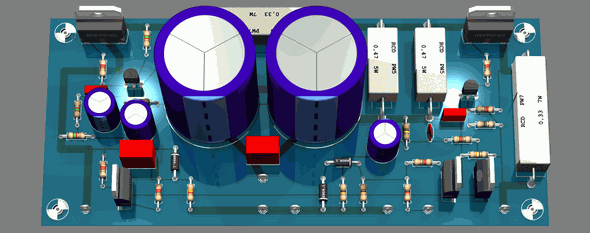
Below on figure 11 is the Complete Breadboard Power Supply with Components.

Figure 11: The Complete Breadboard Power Supply with Components.
You can download the Gerber files of this project for free or you can simply order the PCB of this project from this link: https://www.pcbway.com/project/shareproject/Breadboard_Power_Supply_5V_3_3V.html
Each time a person orders this PCB, we will get 10% commission of the total PCB cost. That’s how you can also support us for more tutorials.
You can download the Proteus Schematic design below here. The file is zipped, you will need to unzip it (Download a free version of the Winzip utility to unzip files).
Proteus Schematic: Breadboard Power Proteus


Không có nhận xét nào:
Đăng nhận xét