Thứ Hai, 17 tháng 12, 2018
4X40 Watts 4 Channel Audio Amplifier Board DIY TDA7388/CD7388 IC

This is TDA7388 4 Channel IC Audio Amplifier Board. this project can play up to 4 X 40 watts speaker easily.
I used CD7388 IC and 0-12 transformer for this project
Materials for the Project
- TDA7388 goo.gl/x1M65m
- cd7388cz goo.gl/W4StkD
- 1uf 50v capacitor goo.gl/nGsiAP
- 47uf 25v capacitor goo.gl/dpeVsK
- 4700uf 50v capacitor goo.gl/ea11Sx
- 0.1uf 100v capacitor goo.gl/hkVbHA
- 6A4 Diode(6a10) goo.gl/SC8ok1
- 2.2K Resistance goo.gl/3DnQMj
- Screw Terminal 5mm goo.gl/hXy8pN
- potentiometer 50K OR 47K goo.gl/hxhYJ7
- 1/4W 10K goo.gl/4wjmt9
100 Watts Stereo Amplifier Board DIY TDA2030 IC with Transistors

This is 100 Watts Stereo Amplifier Board. this project can play up to two 50 watts speaker easily.
I used TIP41C & TIP42C Transistor with TDA2030 IC and 0-30 transformer with 5 amps for this project
Components for the Project
· 6 Resistors 56K
· 2 Resistors 1Ohm1/2W
· 4 Resistors 1.5_2W
· 2 Resistors 3.3K
· 2 Resistors 33K
· 1 Resistor 10K
· 4 Capacitors 2200UF50V
· 6 Capacitors 0.22uf = 224
· 2 Capacitors 10uf
· 2 Capacitors 2.2uf
· 2 Capacitors 22uf
· 4 Diode 1N4007
· 4 Diode 6A4
· 2 IC TDA2030
· 2 Transistors TIP41C
· 2 Transistors TIP42C
· 6 Jumpers
· LED
· 1 Connector 6pin_2.54mm
· 1 Connector 3pin_2.54mm
· 1 Connector 2pin_5mm Screw
· Connectors 2pin_3.96mm
2800W High Power Amplifier Circuit [Updated!]
Mono high power amplifier circuit is actually powerful, output about 1400 W, but if this high power amplifier circuit is doubled and you want to create stereo power amplifier, this high power amplifier circuit the necessary components and PCB requires two-fold. So if the stereo high power amplifier 2 X 1400W Power Output ( 2800W ).
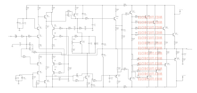
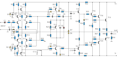
Power Amplifier Circuit Diagram is still less by looking at the circuit that was so below, the finished circuit has been added with gains, using two JRC4558 IC the picture IC where it can be seen below. For circuit buffers, drivers, and booster use multiple transistors and other components (can be seen listed component). And high power amplifier project that is so below is just part of the buffer and driver while the booster has not been made. For additional transistors in the booster or high power amplifier, end scheme can be found Booster output power amplifier. For bass booster using this circuit:
High Power Amplifier PA schematic diagram:
2800W high power audio amplifier circuit diagram
Part List :Power Amplifier Circuit Diagram is still less by looking at the circuit that was so below, the finished circuit has been added with gains, using two JRC4558 IC the picture IC where it can be seen below. For circuit buffers, drivers, and booster use multiple transistors and other components (can be seen listed component). And high power amplifier project that is so below is just part of the buffer and driver while the booster has not been made. For additional transistors in the booster or high power amplifier, end scheme can be found Booster output power amplifier. For bass booster using this circuit:
High Power Amplifier PA schematic diagram:
2800W high power audio amplifier circuit diagram
Resistor
R1_____560ΩR2_____100Ω
R3_____2K2Ω
R4_____560Ω
R5_____1Ω
R6_____27KΩ
R7_____10KΩ
R8_____100Ω
R9_____100Ω
R10____100Ω
R11____12KΩ
R12____100Ω
R13____100Ω
R14____100Ω
R15____27KΩ
R16____2K2Ω
R17____560Ω
R18____100Ω
R19____10KΩ
R20____330Ω
R21____47Ω 2W
R22____56Ω
R23____2K2Ω
R24____22Ω
R25____56Ω
R26____180Ω
R27____500-1KΩ Trim
R28____560Ω
R29____56Ω
R30____56Ω
R31____22Ω 1W
R32____5Ω6 2W
R33____10Ω
R34____180Ω
R35____100Ω
R36____22Ω 2W
R37____180Ω
R38____56Ω
R39____47Ω 2W
R40____5Ω6 2W
R41____10Ω
R42____10Ω
R43____10Ω
R45____10Ω
R46____0.22Ω 5W
R47____0.22Ω 5W
R48____0.22Ω 5W
R49____0.22Ω 5W
R50____10Ω 5W
Capacitor
C1_____1цFC2_____1.5nF
C3_____0.1цF 250-275V
C4_____0.1цF 250-275VC5_____100nF
C6_____100цF 50V
C7_____39pF
C8_____330pF
C9_____330pF
C10____330pF
C11____47nF 250-275V
C12____220nF 250-275V
Transistor
T1_____MJE340T2_____2N5551 / C2240
T3_____2N5551 / C2240
T4_____2N5551 / C2240
T5_____2N5551 / C2240
T6_____2N5401 / BF423
T7_____2N5401 / BF423
T8_____2N5401 / BF423
T9_____2N5401 / BF423
T10____MJE350
T11____B1186
T12____TIP127
T13____D1763
T14____D1763
T15____B1186
T16____C5198
T17____A1941
T18____2SC2922 / MJ15024G
T19____2SC2922 / MJ15024G
T20____2SA1216 / MJ15025G
T21____2SA1216 / MJ15025G
Buy these parts, go to Allchips.
Installation with booster

Password RAR: elcircuit.com
File is using to edit schematic and making Layout PCB by using Proteus Software
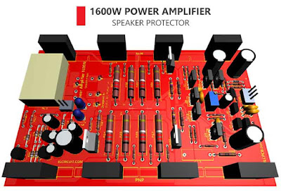
1600W Power Amplifier + Speaker Protector
Power amplifier with high power output that is greatly needed by many audiophiles. Especially for field or concert, and in addition to the SPL car audio designation. Eg for controlling the use of extreme subwoofer speakers. So it takes a lot of power.
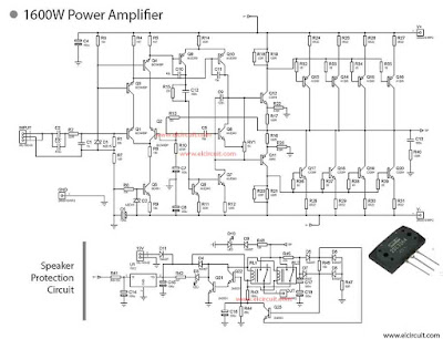
And the following is a power amplifier circuit that can generate output power up to 1600Watt at 4Ohm speaker load. In addition to having a large power, the power amplifier is already equipped with the protection of speakers. The function of the protection speakers is that the speakers are protected by DC voltage which can damage the speakers. It also can cut off the output current when the circuit occurs, so the power amplifier circuit remains safe.
Back to the discussion of this power amplifier. This power amplifier uses 4 final sets of 2SC3264 and 2SA1295 transistors. Where each transistor can flow current up to 18A and has power 200W.
To get a large power, the role of power supply amplifier is very important. Power supply for this amplifier at least 20A with max voltage 100V.
Below is the circuit scheme of 1600W Power Amplifier + Speaker Protector
Material's
| C1 | 1n |
| C2-C3 | 470n |
| C4-C6,C14 | 100u |
| C7,C15-C18 | 100u |
| C8 | 18p |
| C9 | 100n |
| C10-C11 | 10p |
| C12 | 150n |
| C13 | 100n |
| R1 | 33k |
| R2 | 220R |
| R3,R8,R46,R48 | 10k |
| R4-R5,R42 | 4k7 |
| R6,R9 | 18k |
| R7 | 10R |
| R10 | 470R |
| R11-R12,R14 | 100R |
| R13 | 15k |
| R15 | 22k |
| R16-R17,R40 | 100R |
| R18-R21 | 120R |
| R22-R23 | 470R |
| R24-R31 | 0R22 |
| R32-R39 | 1R |
| R41 | 6k8-10k |
| R43 | 180k |
| R44 | 68k |
| R45 | 47k |
| R47 | 82R |
| U1 | 7812 |
| Q1-Q4 | BC546BP |
| Q5 | BD681 |
| Q6-Q8 | MJE340 |
| Q9-Q10 | MJE350 |
| Q11 | A968 |
| Q12 | C2344 |
| Q13-Q16 | A1295 |
| Q17-Q20 | C3264 |
| Q21-Q23 | 2N5551 |
| D1 | MZD15 |
| D2 | MZD18 |
| D3,D10 | LED |
| D4-D9,D11 | 1N4007 |
| 12V | SIL-100-02 |
| GND,OUT,V+,V- | 26630101RP2 |
| INPUT | SIL-100-03 |
| RL1-RL2 | |
| RV1 | 5K |
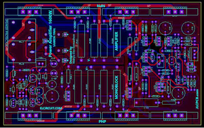
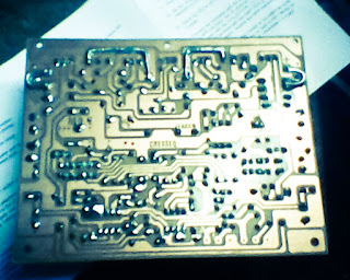
PCB LAYOUT DESIGN POWER AMPLIFIER 2 Layer's
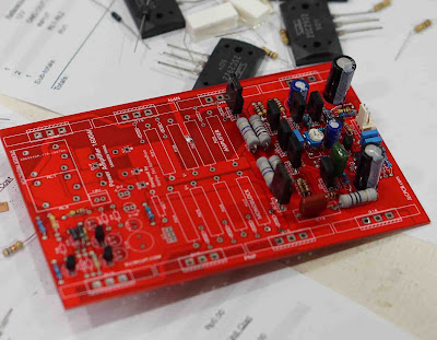
Assembling power amplifier blazer with PCB Double layer
XR2206 Function Signal Generator DIY Kit
Bluetooth Power Amplifier Board
Banggood App download (to get 10% off coupon)
PCB Layout 1600W Power Amplifier PDF
Bill of materials 1600W Power amplifier + speaker protector
Gerber files power amplifier + speaker protector
Đăng ký:
Nhận xét (Atom)
Bài đăng mới nhất
ALEPH-M CLASS A ANFİ DEVRESİ N KANAL MOSFET
Aleph-M çıkış gücü yaplaşık olarak 35w Class A sınıfı anfi için oldukca iyi bir değer çıkış modfetleri n kanal 2 adet irfp240 kullanılmış be...
Bài đăng phổ biến
-
Here is Electronics I course from South Dakota School of Electronics. These lectures cover the mathematical side of how various circu...
-
This is my project about Power Amplifier SOCL504, which I applied for the use of 2.1 (stereo + subwoofer) speaker system. Why am I using thi...
-
In this post I will only share the schematic circuit of Yamaha PA-2400 power amplifier, the Power Amplifier is very tough that has power up ...
-
Introduction Drip irrigation system is a type of micro-irrigation of soil which has the potential to save water and nutrients by allo...
![Layout design high power amplifier [Edited Version] Layout PCB high power amplifier [Edited Version]](https://blogger.googleusercontent.com/img/b/R29vZ2xl/AVvXsEiW7Ie8AEt27bTmYhgi3wTDBrMqt-ysen7JyHDV_xvn3PTjRT7XraqiB3-c0rHxzPcPzJClms1lnDBBAVtW6dxFz-mgvcVDQWF5bKb0Xn3LfHpHJEKRGDd4tPm0-TChIXzoiH6Vek7yi3k/s320/Layout+High+power+amplifier.jpg)
