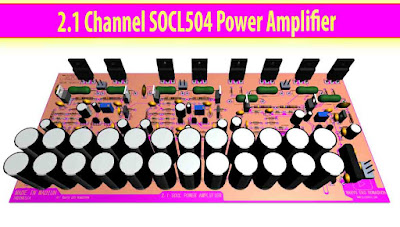
This is my project about Power Amplifier SOCL504, which I applied for the use of 2.1 (stereo + subwoofer) speaker system. Why am I using this SOCL504 driver for the use of 2.1 speaker channels? Yes, because the power amplifier driver is very suitable for use in various places, both in the homeroom and outdoors. And for the sound produced is also very satisfactory. Adopted from a variety of modifications SOCL504 power amplifier, this circuit highly recommends for you who like to make audio power amplifier.
And below for the SOCL504 power amplifier circuit that I combine to get a power amplifier with a 2.1 channel speaker system.
Circuit Description
There are 3 sets of power amplifier SOCL 504, in the blue and green line is using for stereo (satellite speaker's) and the red line is using for subwoofer speaker. The 3 power amplifier SOCL504 I have prepared for its preamplifier you can see here: 2.1 Channel Preamplifier.
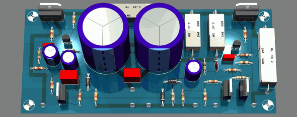
The difference between the stereo and the subwoofer amplifier is found in the capacitor of the A1837 and C4793 driver transistors. For stereo power amplifier I use 220pF and my subwoofer uses 100pF. What is the purpose?
The goal is to place high-frequency output. The higher pico size of the capacitor, the high tone gets bigger so the treble sound will get out but its make more noise also. And the right value is 220pF and the subwoofer amplifier uses 100pF.
In addition to capacitors, the final transistor is also different. Only in number, for stereo amplifiers use 1 set 2SC5200 2SA11943 and subwoofer amp using 2 final sets of transistors. It aims to distinguish the output power and power amplifier power to control the small or large power speakers. And obviously for subwoofer speakers will need more power so that I put 2 pieces of the final transistor for the subwoofer amplifier.
The power supply uses a bridge diode that I give the capacitor to filter and coupling AC to DC circuit. and my capacitors bank and filters use 24 x 680uF - 1000uF / 100V and 4 x 100N / 275V. The input AC voltage is very wide, starting from 20V AC - 75V AC CT.
Specifications
Speaker impedance: 4-8ohm
Supply voltage: AC 20-75V CT MIN 10A
Final Transistor: Toshiba 2SC5200 NPN, 2SA1943 PNP
Channel: 3 channel (left, right, subwoofer) using this 2.1 Preamplifier Circuit
Total Output power: 200W * 2 + 600W * 1 subwoofer (Upgradable)
Output matching: 4-8 ohm
Frequency response range: 14-100khz
2 Layers PCB Layout SOCL504 Power Amplifier
PCB Size 300mm x 135mm
For its PCB I provide 2 files that are in PDF format and Gerber RS274-X. Please download later at the end of the post. For pdf format, you can make it in double layer PCB with black and white picture top and bottom, make your own PCB tutorial you can see on my youtube channel video list. And for Gerber files, you can upload and order to PCB Prototype sites I highly recommend that PCBWay.com. Why PCBWay is recommended?
Because PCBWay is the most professional PCB manufacturer for prototype and low volume production. With more than a decade in the field, PCBWay committed to meet the needs of customers from various industries in terms of quality, delivery, cost-effectiveness and other requests. As one of the PCB manufacturers and the most experienced SMT Assembler in China, PCBWay is strongly recommended to be your friend in terms of PCB production and component assembly. For ways to upload and order you can see in the video below along with designing the PCB.
Complete Video Power Amplifier SOCL504 for 2.1 Channel Speakers.
Download
Gerber RS-274X: 2.1 Channel Power Amplifier SOCL504 GERBER RS274X
PDF : Stereo + Subwoofer Power Amplifier SOCL504
Password: elcircuit.com
Password: elcircuit.com


Không có nhận xét nào:
Đăng nhận xét